Teknion Blink Chair
Formway
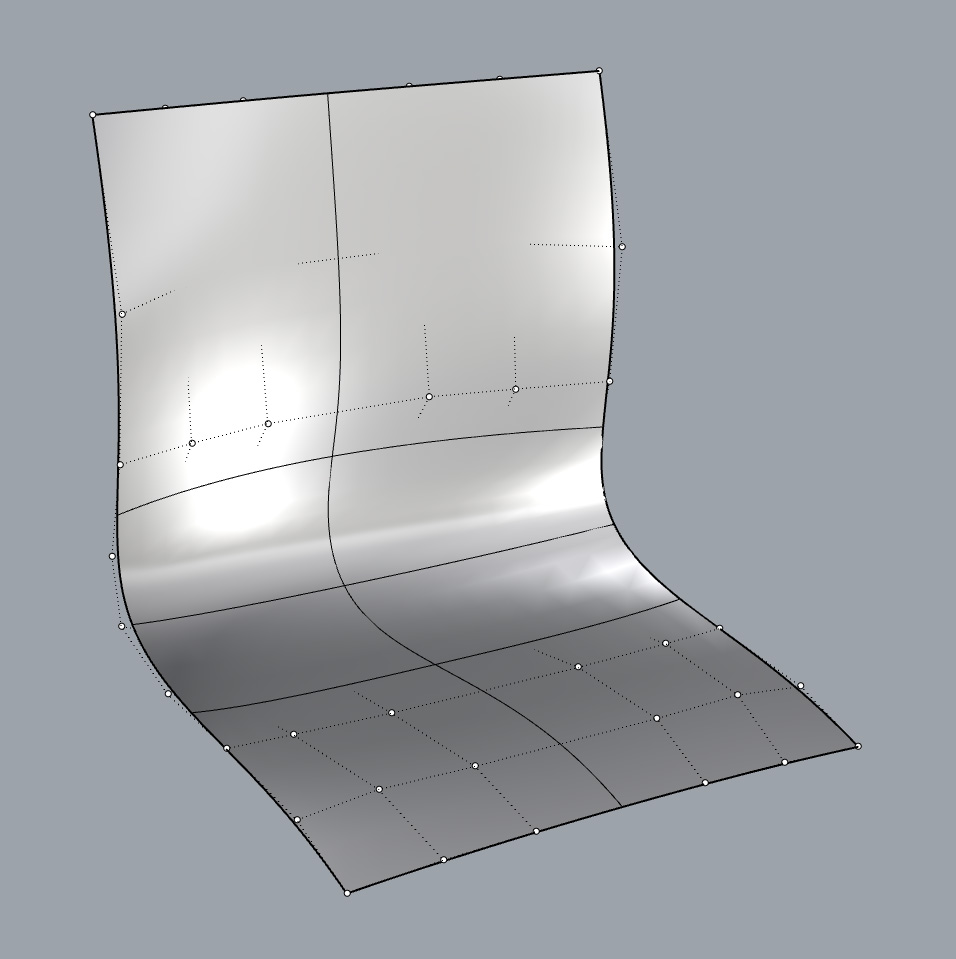
As a very challenging project, the Blink seat shell required a hybrid approach to realise the tool-ready final geometry. The master A side and B side surfaces were created in Rhino. The B surface (rear) was also used within Solidworks to develop the under seat structure, ensuring the structure and seat shell parts matched. The Rhino surfaces were inserted into Grasshopper along with grid reference geometry, which formed the basis of the Grasshopper pattern.
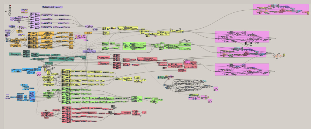
The Grasshopper definition defined the core geometry of the seat shell pattern, including slots, cells, draft, radii, all which had to fall within the draft criteria (one line of draw for the A side/front and 3 lines of draw for the B side/rear). Bitmaps were used to control variable dimensions across the shell, including wall sections/thicknesses.
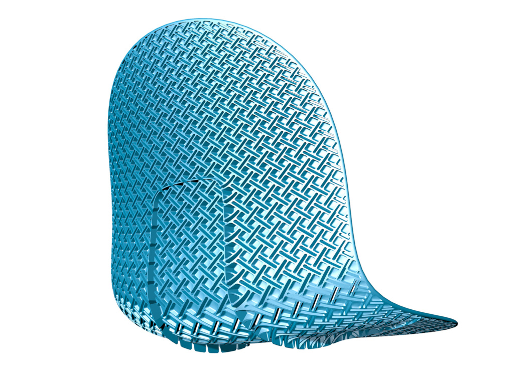
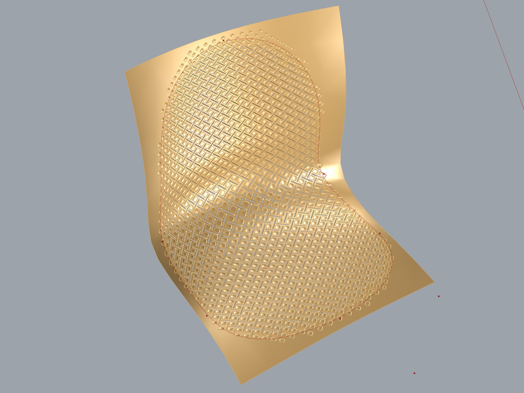
The resulting A side pattern, geometry generated in Grasshopper.
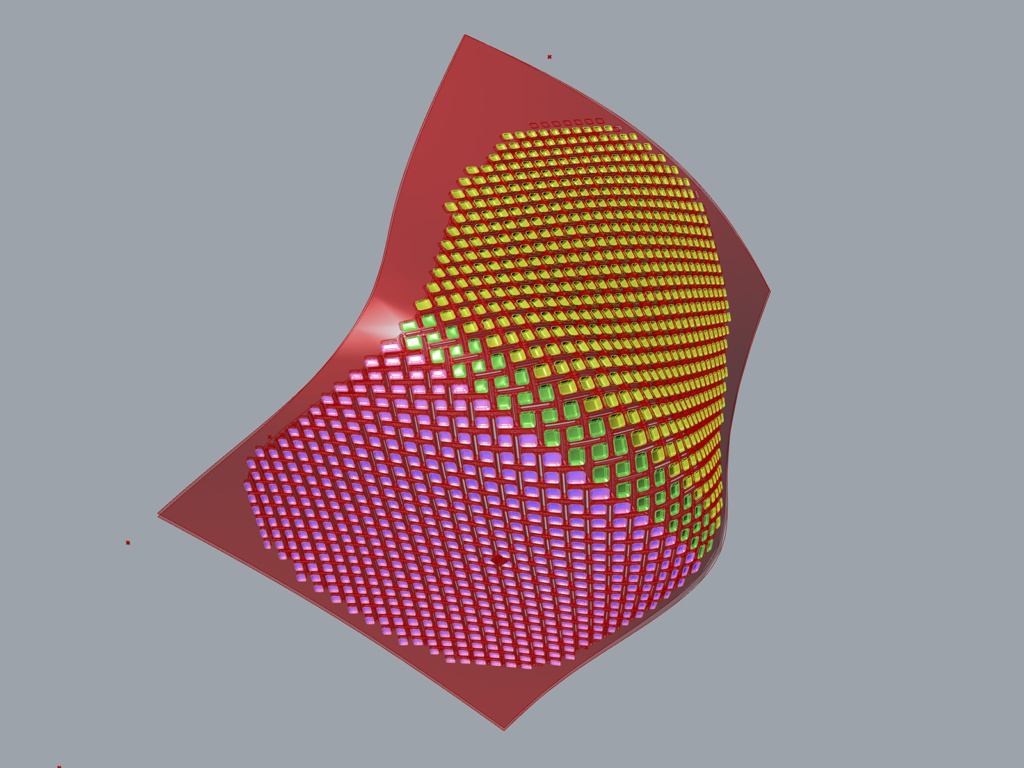
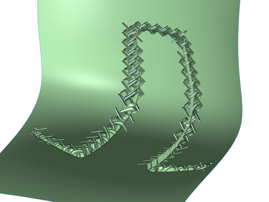
The resulting B side pattern, geometry generated in Grasshopper. The three different colours show the three different lines of draw needed to mould the rear pattern.
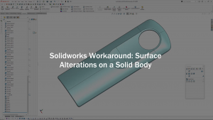
The Grasshopper geometry was baked and then exported into Solidworks, where the fingerguard detail (below) was modelled. The decision was made to model this in Solidworks in case tweaks needed to be made to the geometry. Only the slots and cells that were in the vicinity of the finger guard were imported into Solidworks, to keep the model lightweight.
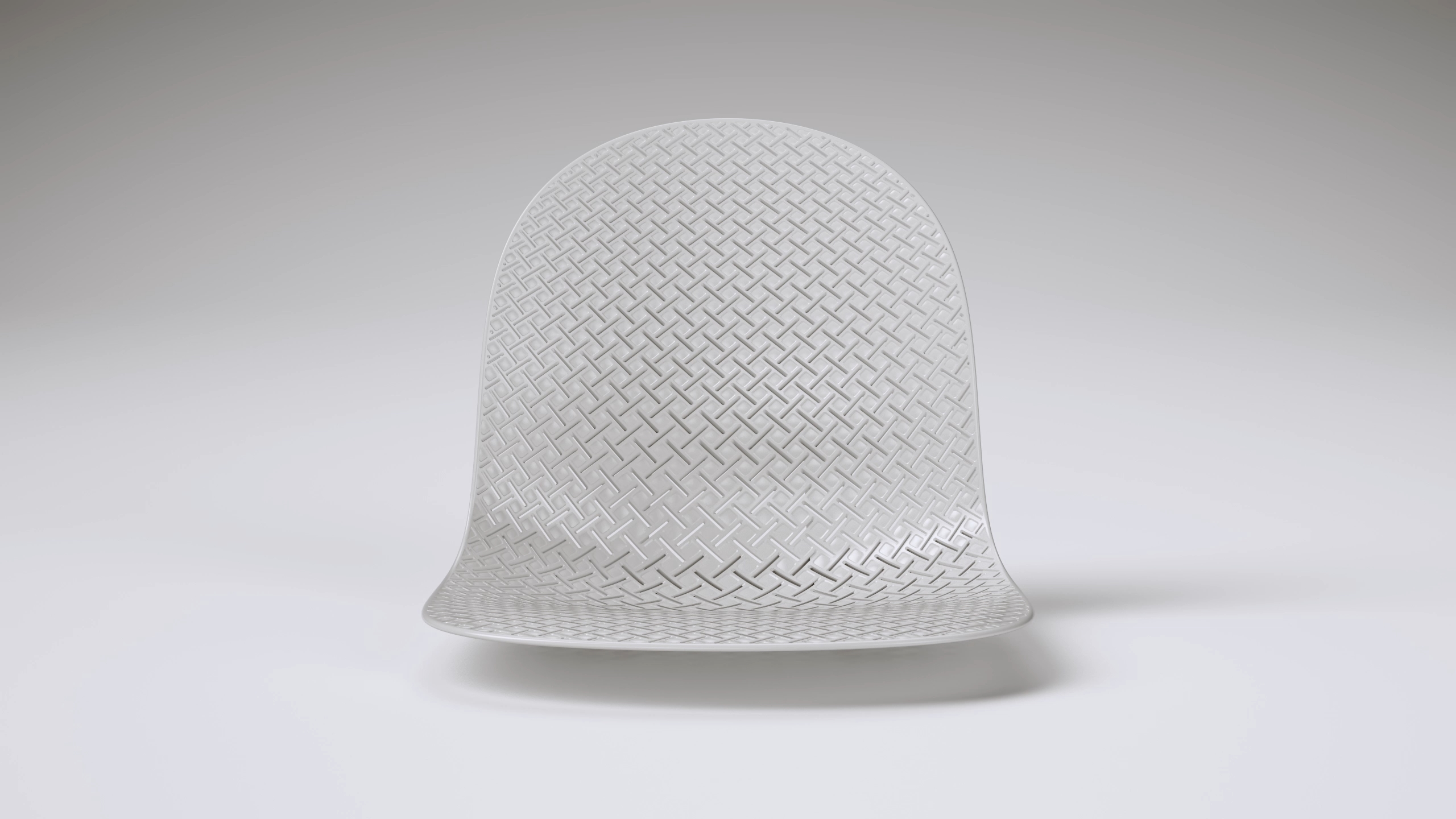
Once the finger guard had been modelled in Solidworks, the geometry was inported back into Rhino, where it was integrated with the rest of the seat shell pattern. Final A side below.
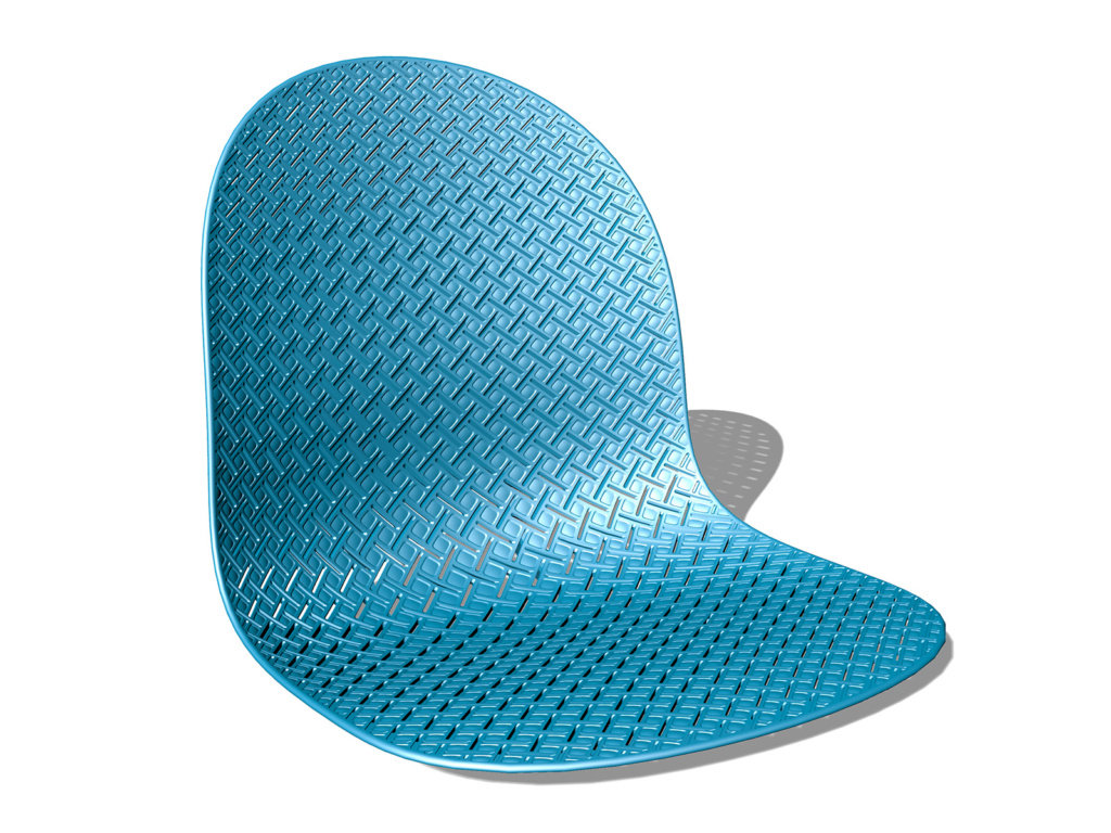
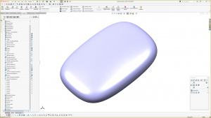
The geometry was then exported again into Solidworks, but this time as a complete seat shell. Additional details for moulding and assembly were added in Solidworks. Final B side below.