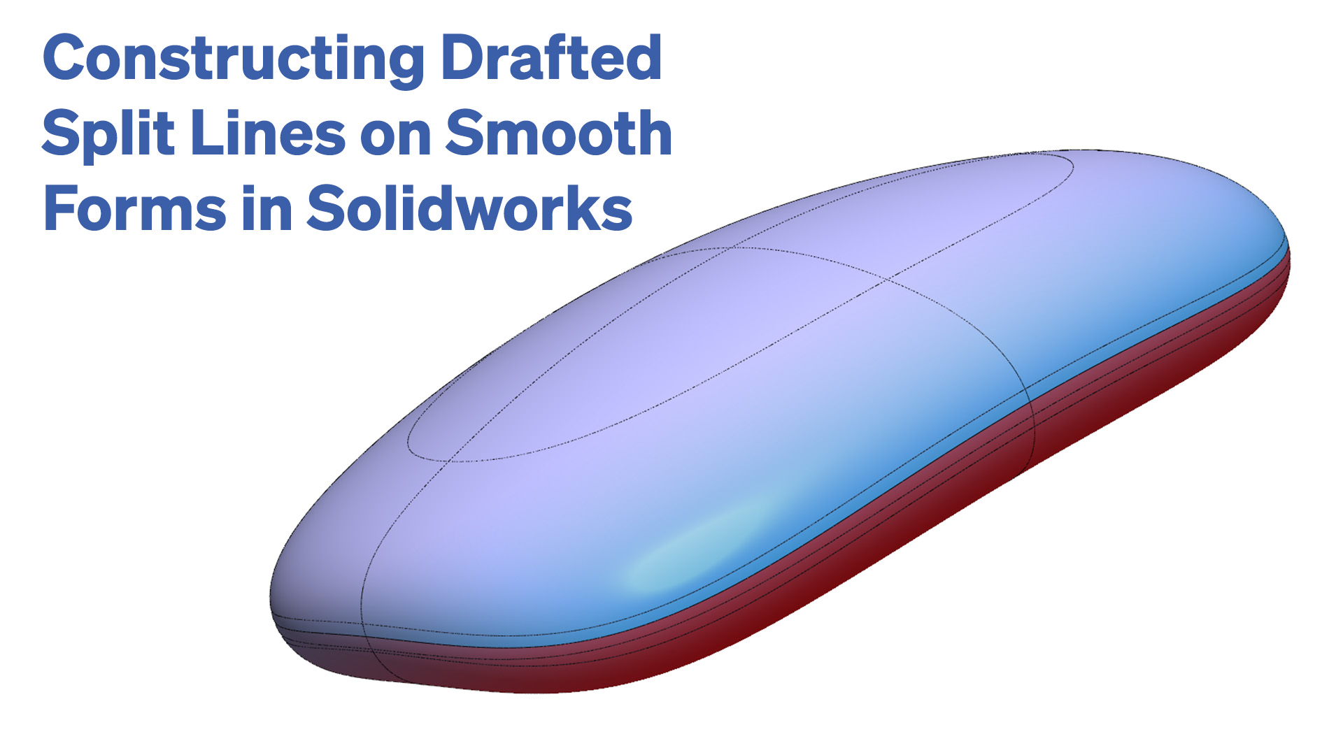
In this exercise I cover two ways to construct a drafted split line on a smooth form, where the form has not been modelled with an explicit split line. Both methods use Solidworks surface modelling.
The first method uses silhouette split lines to find the positive and negative draft boundaries, then ruled surfaces to reinstate the form up to the split line. This results G1 continuity between the primary surfaces and the ruled surface.
The second method also uses silhouette split lines, but in this case they are used to create relief or setback trims of the primary surfaces. Boundary surfaces are then constructed between the primary surfaces and drafted helper surfaces, with the result being G2 continuity between the primary surfaces and the blends on the positive and negative side of the split line.


